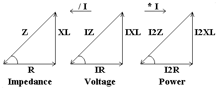
R and L in series:
The voltages dropped across the inductor and the resistor must be added together using phasor summation, i.e. adding the two voltages as they would be shown on a phasor diagram, if the second phasor is drawn starting from the end of the first phasor. Since VL is at right angles to VR then the components are added using pythagoras's theorem, a2 = b2 + c2.The triangle this makes shows the voltages VR and VL, and the total voltage V on the hypotenuse (see below).
Since V = IZ, dividing all the sides by I gives R, XL and Z, the impedances.
Similarly, multiplying all sides by I gives I2R, I2XL and I2Z , the power dissipated in the components.
The term impedance (Z) is used for the combination of component resistances and reactances, e.g. the 'circuit impedance' refers to the total impedance of a circuit containing a number of resistors, inductors and capacitors whose resistances and reactances have been combined using phasor summation.

Phase Angle:
The angle between the adjacent and the hypotenuse of the triangles is the phase angle of the combined components. I lags V.f = cos-1 (R/Z)
R and C in series:
As for R and L in series, except that for the phase angle of the two combined components, I leads V.R, L and C in series:
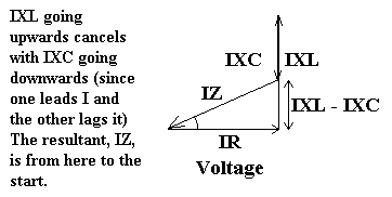
This can be visualised from drawing all 3 components on a phasor diagram. The resistance is in phase, therefore it's phasor will be horizontal. The inductance will then have it's phasor going upwards, but the capacitance phasor will come down again from this point. The hypotenuse of the triangle is from the end of the capacitance phasor back to the start. This hypotenuse is the resultant voltage drop.
Again, the values can be divided and multiplied by I to give impedance and power respectively.
V2 = (VR2 + (VL - VC)2)
Take the square root of these to get the voltage dropped, V.


